Frequency Voltage Converter Circuit Diagram Frequency Conver
Frequency voltage converter using circuit fsr input 5v hz set datasheet range given signal trying stack Circuit diagram of frequency to voltage converter. 2 simple voltage to frequency converter circuits explained – homemade
[SOLVED] voltage to frequency conversion
Build a voltage to frequency converter circuit diagram 3 Frequency voltage conversion classical solution Build a voltage-to-frequency converter circuit diagram 2
Converter frequency voltage circuit diagram build circuits output electronic
Frequency converter circuit diagram2 simple voltage to frequency converter circuits explained – homemade Converter voltage frequency dual supply circuit ic based version3 frequency to voltage converter circuits explained – homemade circuit.
[solved] voltage to frequency conversionFrequency to voltage converter: a proportional mechanical to electrical Voltage frequency converter circuitsFrequency to voltage converter circuits explanation.
Frequency diagram voltage converter circuit schematic
The stable performance range of a simple frequency-to-voltage converterVoltage to frequency converter circuit using ca3130 Voltage converter frequency circuit diagram circuits simple requency gr nextFrequency to voltage converter circuit using 555.
Frequency converter voltage circuit circuits simple homemade scale full detection explained resistorFrequency converter voltage circuit using ca3130 figure volts eleccircuit input Frequency to voltage converter circuit diagramConverter frequency circuit circuits explanation.

Converter frequency voltage simple diagram circuit
Voltage to frequency converter circuit diagramFrequency to voltage converter circuit diagram Circuits diy frequency to voltage converter circuit using lm331 icSimple frequency to vvoltage converter circuit diagram.
Voltage converterConverter frequency circuit circuitstoday Voltage converter circuit frequency frquency diagramConverter frequency voltage circuits ic homemade explained.

Build a frequency voltage converter circuit diagram
Frequency to voltage converter circuit diagramVoltage converter circuit diagram frequency simple ic circuits build gr next Frequency to voltage converter circuit diagramVoltage to frequency converter.
Frequency converter circuit diagram simple circuitsSchematic of the proposed voltage to frequency converter. Frequency to voltage converter circuit [] diagram guideFrequency to voltage converter.
Circuit frequency converter circuits schematic breadboard demonstration modify were
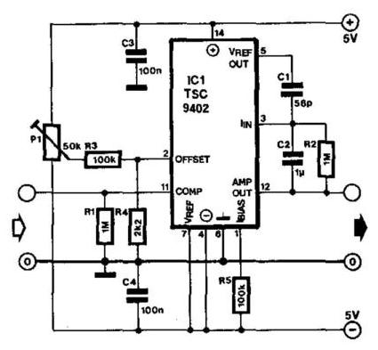
Voltage to frequency converter circuitVoltage converter frequency circuits microcontrollerslab input networks output mikrocontroller integrator khz funktioniert wandler Frequency to voltage converter circuit based on the tc9400 icFrequency to voltage converter circuit based on the tc9400 ic.
Frequency voltage converter circuit diagram circuitsVoltage frequency converter circuit diagram schematic circuits dc using control simple gr output next seekic source voltages differential negative accept Simple frequencyVoltage to frequency converter circuit using ad654.

Frequency converter voltage circuit diagram electroschematics audio ca3130
Voltage to frequency converter – simple circuit diagramVoltage frequency converter circuit diagram build Diy voltage to frequency converter circuit.
.


![[SOLVED] voltage to frequency conversion](https://i2.wp.com/obrazki.elektroda.pl/4493642200_1366955217.png)


